Wednesday, August 23, 2017

Virtualization: The technology behind cloud

Virtualization is the dominant technology used to set up cloud environment. In traditional approach, without using virtualization technology, only one OS can be installed onto one physical machine. However, using virtualization technology, multiple machines can be created, called Virtual machines (VMs) or virtual server. In research articles, PMs are also referred to physical servers. Similarly, the physical resources are also refers to substrate resource. Now, lets understand the figure given below.


Fig: Type-1 and Type-2 hypervisor
[src]: https://commons.wikimedia.org/wiki/File:Hyperviseur.png#/media/File:Hyperviseur.png


The virtual machines can be created only with the help of a small piece of software call virtual machine monitor (VMM) or virtual manager that implements the virtualization technology. The VMM can be installed directly on the hardware (Type 1 in the above figure) or can be installed atop an OS (Type 2 in the above figure). When the VMM is installed atop an OS, that OS is called hosted OS and the OS that is installed in each virtual machine is called guest OS. This virtualization layer provides and environment for the VMs to interact with the hardware. Another major responsibility of virtualization layer is to maintain the isolation among the VMs or guest OSs.

Here question arises, how this technology helps us to setup a cloud environment. When the cloud user ask for a computer with the configuration 2GB memory, 2 processing units, 50GB storage, and 2mbps network connection, cloud service provider creates a VM with the configuration provided by the cloud user. The cloud user is than given a URL in order to establish a connection to the created VM. Cloud user has no information regarding the underlined PM upon which the VM is created. In general CSPs adopt the TYPE 1 (in the above figure) approach to create the VMs. multiple VMs are created upon single PM. Another major advantage of this virtualization technology is that, it is very easy to migrate a VM fromone PM to another. Users are also NOT given any facility to interact with the physical machine which make the PMs more secure from the outside attacker.

Here is the link to calculate the number of VMs per PM or Host. In today's date an average of 40-60 VMs are created on each PM.

Based on the where the VMM is installed and purpose of the installation, virtualization is of four types[1].
    1. Hardware Virtualization : If the VMM is install atop the hardware, e,i, Type 1 in the above figure
    2. OS Virtualization : If the VMM is install atop an Operating System, e.i. Type 2 in the above Figure
    3. Storage Virtualization : Here the VMM is installed on multiple storage servers, which forms a single storage system for the user.
    4. Server Virtualization: When the VMM installed to divide the single physical server system into multiple virtual servers.

Besides aforemention four types, virtualization can also be divided into data virtualization, memory virtualization, network virtualization etc categories[2].


Thats all about the basics of Virtualization. Please comment if you need more further detail information.

Thank you

Tuesday, June 27, 2017

Cloud computing for layman


Before digging to the concept of cloud computing, Let's see how we consume electricity. Basically in every region some companies/organisations are providing electricity to every house. Electricity provider uses Copper or Aluminium wire to provide eletricity to our houses. In addition to that, external electric meter is attached in every house to monitor the amount of electric power we are consuming.

Now imagine computer instead of electricity. Some organization may offer you computers instead of electricity. Computers will be rented to you over high speed internet by some organization. The computers are not provided physically by shifting the machines to your location, rather, the organizations/providers allow you to connect to that computer over high speed internet. A large number of computers are used by the provider. Those large number of computers, also known as servers, are kept in secure place called Data Center. Henceforth, we will use the term server instead of computer. The organization is called cloud service provider (CSP) and the users are called cloud user. So here we have two entities: cloud consumer/user, and the CSP.

The CSP also provide the software on a rented instead of the server. Let’s say, I want to use MS office. In that case I’ll have two options: either buy the software or rent from the CSP. In later option, you will be allowed to access the software through a webpage or some explicitly designed different interface. Such interface will provide you all the required functionalities and you need to pay based on different costing model. This kind of service offered by the CSP is called Software as a Service (SaaS). For example, Google Apps, Salesforce etc

User may also request the CSP multiple number of servers with certain configuration. For example, One may ask the CSP to provide two servers with 4GB memory, 50GB storage, 4 processing units. Offering such service to the cloud users is called Infrastructure as a Service (IaaS). For example Amazon AWS, Windows Azure, Google Compute Engine, IBM SmartCloud Enterprise, Rackspace Open Cloud etc.

Coming to another type of service, CSP also customize the service based on the users requirement such as providing the platform. Here user refers to the software developer. CSP provides all the required software components, such as database servers, programming environment etc, in order to develop a software tool. Such kind of service is called Platform as a Service, in short PaaS. For example, Google App Engine provides the environment to develop web applications using Java, Python, PHP and Go.

Fig. 1 : Snap of data center’s inside view [src]

Thats all about the basics of Cloud Computing. Next, we will see the underlined technology behind the cloud computing.

-Thank you


Monday, June 19, 2017

Shell Script: Pausing the execution with sleep command

To pause the execution of shell script use sleep command.

Examples:

sleep 1   # Pause for 1 sec
sleep 1s  # Pause for 1 sec
sleep 1m  # Pause for 1 min
sleep 1h  # Pause for 1 hour
sleep 1d  # Pause for 1 day
sleep .1  # Pause for 100 mili-sec i.e. 0.1sec


Thank you

Saturday, June 10, 2017

X11 forwarding using Xming X server for Windows

Problem statement:

Let's say, We have 2 two computers: One with Ubuntu OS and other with Windows OS
Through SSH connection, "How can we access the any application's interface (GUI) installed on Ubuntu computer from Windows computer ?". For example, we want to access the GUI of calculator application that is installed on Ubuntu from Windows computer.

Environment:

First computer:
                       OS- Ubuntu 14.04 64-bit
                       Openssh-server package
Second computer:
                       OS- Windows 8 64bit
                        Xming software tool

Here, for demonstration, we will open GUI of calculator application
The command to open the calculator in Ubuntu is gnome-calculator                      

Step-1:
On Ubuntu Computer, install openssh-server package.

Perform Step-2 to 5 on Windows computer.
Step-2:
On Windows computer: 
Download Xming for Windows 8 64bit.
Install Xming executable file. You don't have to do any changes. Leave everything to the default selection.

Step-3: 
Now open command prompt on Windows computer
Change the directory to the location where Xming is installed. In my case it is "C:\Program Files (x86)\Xming"


cd "c:\Program Files (x86)\Xming"

Step-4:
Now enter the following command to start Xming on Windows


Xming.exe -multiwindow -clipboard


Step-5:
Now its the time to connect to the Ubuntu computer through inbuilt putty. In this step, you need to provide the login information, and the command to open required application.

The command can be

plink -ssh -2 -X user1@<IP of ubuntu computer> -P <port number of SSH server> <command to open the required application>


e.g.

plink -ssh -2 -X chinmaya@120.162.56.85  -P 23 gnome-calculator


Here, I am connecting to the Ubuntu computer through ssh protocol 2.
The IP address and SSH port number of Ubuntu computer is 120.162.56.85 and 23, respectively.
gnome-calculator is the command to open the GUI of calculator application.

After entering the above command, you need to give the corresponding password. If all goes well, the required GUI will appear on Wondows computer.

Please comment if you need more information or if you have any suggestion.

-Thank you


Friday, June 9, 2017

GitLab: For private Git repository

I assume here that the reader has basic knowledge about GitHub, BitBucket or SourceForge or some other alternatives to GitHub. Now, as a member of small research team, my responsibility is to setup something like GitHub in our own private server. The objective is to store and access individual's source code used for varification and evaluation of own research projects in a secure place. It's quite similar to GitHub.

For this requirement,I found GitLab as one of the best solutions. Installation of such software tool is a straight-forward procedure.

Installation Procedures:


Environment

In our physical server, NO other webserver is installed.
OS: Ubuntu 14.04, 64-bit Desktop version

Step-1:
Open the terminal by pressing Alt + Ctrl + T.

Step-2:
Enter the following command
sudo apt-get install curl openssh-server ca-certificates postfix
 
 This will install curl to get download the required packages, openssh-server for secure connection, postfix to setup mailing server and other essential packages.

Step-3: 
Now run the following commands donwload and install community edition of GitLab
curl -sS https://packages.gitlab.com/install/repositories/gitlab/gitlab-ce/script.deb.sh | sudo bash
sudo apt-get install gitlab-ce

Pre-Final Step:
Reconfigure the gitlab-ce and start the GitLab server by running following command
sudo gitlab-ctl reconfigure

Final Step:
Once the server is ready, please open any web browser. Visit http://127.0.0.1 or http://localhost or http://<The IP of own server>
At first, enter the new password for the administrator. Once the password for the administrator is setup, other usernow can signup their account and enjoy own git repository.

For more information please visit GitLab official homepage.


-Thank you


Friday, May 12, 2017

Fixing WinEdit MDI event handler macros error.

Environment
     OS: Windows 7 32bit
     WinEdit v5.4 (build: 20050201)

Error :


Possible Reason: 
     Either the path mentioned is wrong OR the macro file "MDIOpen.edt" is accidentally deleted.

How to Fix this Issue?
 Follow below steps

1.  Open WinEdit 5.4 program.
2.  Go to "Options" menu and select "Preferences" submenu.
3.  Click on "MDI Events" tab.

4.  Now check all four paths. The directory of all files (MDIOpen-Before.edt, MDIOpen.edt, MDIActivate.edt and MDISave.edt) must be same.

Here %b represent "C:\Program Files\WinEdt Team\WinEdt" path.
Now let's check two directories:
                 First  "C:\Program Files\WinEdt Team\WinEdt\Macros"
                 Second: "C:\Program Files\WinEdt Team\WinEdt\Macros\Events"

First Directory  "C:\Program Files\WinEdt Team\WinEdt\Macros ": 

Second Directory: "C:\Program Files\WinEdt Team\WinEdt\Macros\Events"


Now it is clear that the path in  MDI Events preference is WRONG.

5. Change the path from "[Exe("%b\Macros\MDIOpen.edt");]"  to "[Exe("%b\Macros\Events\MDIOpen.edt");]".


6. Now, restart the WinEdit program. Hope the error is fixed.

Let me know in the comment section if the error is NOT fixed.

-Thank you


Friday, April 28, 2017

What is Fat Tree and how to construct it in 4-steps ?

Fat tree network topology looks like a tree topology like below example. In tree topology, we have same terminologies like Root, parent, child etc.  This is mainly used to connect a large number of physical servers/ computers in a large data center.
Fig-1. An example of tree network topology


It is recommended that reader should go through the basics of cloud computing and data center first.

In the tree structure topology, leaf nodes are physical servers or computers. Rest other nodes are switches.

Switches are basically 3 types: Core switches, Aggregation switches, and Edge switches.
Servers can be heterogeneous in terms of their configurations.

Fat tree topology is based on the complete binary tree. Below is an example of 3 layer Fat tree topology. The top layer (level-0) of switches is called Core layer. The second layer of switches is called Aggregation layer. And the third layer of switches is called Edge layer. The number of ports in each switch is same.

Fig-2. An example of 3 layer Fat tree topology.
Now let's construct a Fat tree network.
The information we need is the number of ports present in each switch. Let k be the number of ports that each switch contains. Switches with k number of ports in a Fat tree topology is called k-ary or k-port Fat tree network topology.
From the value of k, we’ll derive the number of core switches, aggregation switches, edge switches and the maximum number of servers that can be attached.
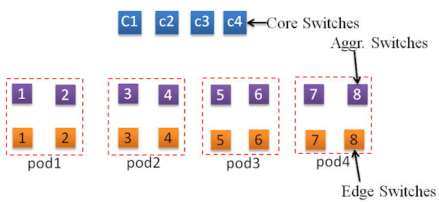
A set of (k/2) number of aggregation switches and (k/2) number of edge switches are combined together and that is known as a Pod.

Example - 1:

Let k=4, i.e. each switch has 4 ports.

Step-1:                                          
    Number of core switches is (k/2)^2 = 4 core switches.  If the value of k=8, we need (8/2)^2=16 core switches.
    Number of pods = k = 4.
Fig-3. Step-1 of Fat tree construction

Step-2:                                          
    Each pod consists of (k/2)=(4/2)=2 aggregation switches and (k/2)=(4/2)=2 edge switches.
    The switches are organized in layer wise. First layer is aggregation layer. Second layer is edge layer.
Fig-4. Step-2 of Fat tree construction


Step-3:                                          
    Each aggregation switch within a pod is connected to (k/2)=(4/2)=2 core switches and (k/2)=(4/2)=2 edge switches.
Fig-5. Step-3 of Fat tree construction

Step-4:                                          
    Each edge switch within a pod is connected to (k/2)=(4/2)=2 servers and (k/2)=(4/2)=2 aggregation switches. That means each pod will be connected to (k/2)^2=(4/2)^2=4 servers.
    Hence the maximum number of servers that can be connected to the network is (k^3)/4=16 servers.
Fig-6. Step-4 of Fat tree construction


Example - 2:

If the value of k=8, each switch has 8-ports.
Step-1:                                           
    Number of core switches is (k/2)^2 = 16 core switches.
    Number of pods = k = 8.

Step-2:                                           
    Each pod consists of (k/2)=(8/2)=4 aggregation switches and (k/2)=(8/2)=4 edge switches.
    The switches are organized in layer wise. First layer is aggregation layer. Second layer is edge layer.
  
Step-3:                                          
    Each aggregation switch within a pod is connected to (k/2)=(8/2)=4 core switches and (k/2)=(8/2)=2 edge switches.

Step-4:                                          
    Each edge switch within a pod is connected to (k/2)=(8/2)=4 servers and (k/2)=(8/2)=4 aggregation switches. That means each pod will be connected to (k/2)^2=(8/2)^2=16 servers.
    Hence the maximum number of servers that can be connected to the network is (k^3)/4=128 servers.


Thats all for now.
Please comment if you need more information.


-Thank you

Tuesday, April 11, 2017

Creating and customizing 3D graph in MATLAB.

Unlike 2D figure, 3 variables are involved in a 3D figure. Below is an example of 3D mesh graph. For certain value of X and Y, we plot the value of Z.
Example :
        Z = (X  /  (c*Y))
3D figure can be bar, mess, surf etc...

Let's begin drawing the graph for the equation
        Z = (X  /  (c*Y))

Step-1: Prepare the data

X = [0.1000    0.1889    0.2778    0.3667    0.4556    0.5444    0.6333    0.7222    0.8111    0.9000]
Y = [-0.1000   -0.1889   -0.2778   -0.3667   -0.4556   -0.5444   -0.6333   -0.7222   -0.8111   -0.9000]
c = 0.05

Here I have used the following Matlab code to generate the data for X and Y.
X = linspace(0.1,0.9,10)
Y = linspace(-0.1,-0.9,10)

for X, 0.1 is the initial value, 0.9 is the final value, and 10 is the number of values to be generated between initial and final value. Similarly for Y also. 


Now In order to generate the data for 3D surf convert X and Y data to a meshgrid.
Step-2: 
           [mx, my] = meshgrid(X, Y);

Step-3: Generate data for Z-axis
           Z = mx ./ (c.*my);

Step-4: Get ready to plot the data onto a 3D figure.

Enter the following code


figure1 = figure();

% Create axes
axes1 = axes('Parent',figure1);
hold(axes1,'on');
% Create xlabel
xlabel('X-axis Label');

% Create ylabel
ylabel('Y-axis Label');

% Create zlabel
zlabel('Z-axis Label');

view(axes1,[152.1 22]);


% Create surf
surf(ax,ay,Z,'Parent',axes1);

grid(axes1,'on');

% Set the remaining axes properties
set(axes1,'FontName','Times New Roman','FontSize',14,'FontWeight','bold',...
    'XTick',[0.1 0.3 0.5 0.7 0.9],'XTickLabel',...
    {'0.1','0.3','0.5','0.7','0.9'});

Final Step:
The entire Matlab file will look like this

X=linspace(0.1,0.9,10);
Y=linspace(-0.1,-0.9,10);
c=0.05;

[ax, ay] = meshgrid(X,Y);
Z = ax ./(c.*ay);

figure1 = figure();

% Create axes
axes1 = axes('Parent',figure1);
hold(axes1,'on');
% Create xlabel
xlabel('X-axis Label');

% Create ylabel
ylabel('Y-axis Label');

% Create zlabel
zlabel('Z-axis Label');

view(axes1,[152.1 22]);


% Create surf
surf(ax,ay,Z,'Parent',axes1);

grid(axes1,'on');

% Set the remaining axes properties
set(axes1,'FontName','Times New Roman','FontSize',14,'FontWeight','bold',...
    'XTick',[0.1 0.3 0.5 0.7 0.9],'XTickLabel',...
    {'0.1','0.3','0.5','0.7','0.9'});


Bonus tips: Customizing the axis label with text() and annotation().

Disable xlabel(), ylabel(), and zlabel() if you are going for text() or annotation() command.

text() example:
% After running this .m file edit the position of each text box
   ty=text(0.5,0.5,'Y-axis label','Rotation',-28,'FontSize',20,...
    'FontWeight','bold','FontName','Times New Roman');

annotation() example:

  annotation(figure1,'textbox',...
     [0.528242677824266 0.789163935354498 0.0753138055985942 0.0475409826782883],...
     'String',{'? = 0.5'},...
     'FontWeight','bold',...
     'FontSize',12,...
     'FontName','Times New Roman',...
     'EdgeColor',[0.24705882370472 0.24705882370472 0.24705882370472],...
     'BackgroundColor',[1 1 1]);

Thats all for now. 
Please comment if more customization function you need.


Thank you